LED Toggle App
This LED app example is for the users who want to use external connectors in WiPhone for GPIO operations. WiPhone has 2 external Pogo Pin Connectors having 11 GPIO pins in total, available at back side of PCB which can be used for variety of daughterboard applications. This tutorial should enable a user to achieve the WiPhone's GPIO input/ output control in firmware for applications via a simple LEDExample App demonstration. We will show you how to configure pogo connectors as GPIO output and turn ON / OFF the corresponding pins from your WiPhone.
- After completing this Example, user will learn how to:
- Change mode of the general purpose input/output (IO) pins
- Connect a button widget to an IO pin
- Write 0 or 1 values to an IO pin
- Get the current status of an IO pin
- Navigate through button widgets vertically and horizontally
- Change color of button widget
Following GPIOs are being controlled/ operated through WiPhone interface.
| Pogo Pin Number | SX1509 - DX | Pogo Pin Number | ESP32 - GPIO |
|---|---|---|---|
| 15 | D0 | 12 | 32 |
| 16 | D1 | 18 | 12 |
| 19 | D2 | 20 | 13 |
| 20 | D3 | 16 | 27 |
| 21 | D4 | 17 | 14 |
| 22 | D5 |

I/O Pins Physical Layout
How it works in WiPhone Interface
The example can be found in Tools -> Development -> Software Examples -> LED Example in WiPhone Menu on Screen. Once you open that app, you will be able to see small red colored rectangles placed and visible within the WiPhone Screen. For simplicity, the orientation of these rectangles and the numbers assigned to them, resembles the orientation of physical Pogo connector pins, placed on PCB board of WiPhone. You can use WiPhone's button keys to switch the places. When you click menu button on any selected pin, the respective pin will toggle itself. In GUI, the Red color will turn into Green or vice versa.
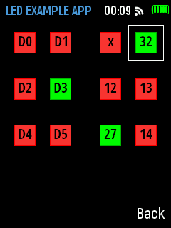
I/O Pins App Layout
Note
GPIO can only support 3.3V operations.
Implementation in Firmware
Identify Major Files & Functions
- GUI.h
- GUI.cpp
- processEvent (EventType event)
- redrawScreen (bool redrawAll)
- typedef enum ActionID : uint16_t {}
- GUIMenuItem menu[xx] PROGMEM = {}
- void GUI::enterApp (ActionID_t app)
Declaring a unique name for your app in GUI.h file
Search for "typedef enum ActionID" method in GUI.h and put your app name "GUI_APP_LEDExampleApp" as Action ID at designated place`.
Adding App Class into Header File
Insert following class code into GUI.h file.
GUI.h:
class LEDExampleApp : public WindowedApp {
public:
LEDExampleApp( LCD& disp, ControlState& state, HeaderWidget* header,
FooterWidget* footer);
virtual ~LEDExampleApp();
ActionID_t getId() { return GUI_APP_LEDExampleApp; };
appEventResult processEvent(EventType event);
void redrawScreen(bool redrawAll = false);
void changeState(int i);
void getState();
int16_t LEDPINS[12] = {EXTENDER_PIN(10), EXTENDER_PIN(11),38, 32, EXTENDER_
, PIN(12), EXTENDER_PIN(13), 12, 13, EXTENDER_PIN(14), EXTENDER_PIN(15), 27, 14}
, ; //put pin values here
bool LEDSTATE[12] = {false, false, false, false, false, false, false, false,
, false, false, false, false};
int sel = 0;
int xold,yold;
protected:
static const int EXIT_CNT = 5;
ButtonWidget* bbKeys[12];
// uint8_t keyPressed[25];
bool anyKeyPressed;
//MultilineTextWidget* details;
bool screenInited = false;
const colorType redBg = 0xf9a6;
// 255, 55, 55
const colorType redBorder = TFT_RED;
const colorType greenBg = TFT_GREEN;
const colorType greenBorder = 0x5c0;
// 0, 185, 0
const colorType yellowBg = TFT_YELLOW;
const colorType yellowBorder = 0xb580; // 177, 177, 0
const colorType greyBg = GRAY_50;
const colorType greyBorder = GRAY_33;
const colorType blueBg = GRAY_50 | TFT_BLUE;
const colorType blueBorder = GRAY_33 | (TFT_BLUE >> 1);
};
Declare and Define App Classes in Main code
Now that we are done with the formalities, This segments will show us a way of adding actual source code of our LED Example. Before doing that in GUI.cpp file, search for GUI::enterApp(ActionID_t app) and append below line in switch statement in designated place as shown.
case GUI_APP_LEDExampleApp:
        runningApp = new LEDExampleApp(*screen, state, header, footer);
break;
The designated place to add above line within the switch statement in code can be found at enterApp Method in GUI.cpp.
Define App Constructor
Next, we declare and define LED Example app class source code in Main cpp file of firmware. Here a a constructor method that we already instantiated in step above, needs to be defined first in GUI.CPP. After that, other related functions to follow in order to fully implement our example App. Let’s add constructor function for class LEDExampleApp.
GUI.cpp
LEDExampleApp::LEDExampleApp( LCD& lcd, ControlState& state, HeaderWidget*
,header, FooterWidget* footer): WindowedApp(lcd, state, header, footer) {
header->setTitle("LED EXAMPLE APP");
for (int i = 0; i < sizeof(LEDPINS) / sizeof(LEDPINS[0]); i++) {
if (i != 2) {
allPinMode(LEDPINS[i], OUTPUT);
}
}
footer->setButtons(NULL, "Back");
this->getState();
// Create all the widgets
const uint16_t spacing = 1;
uint16_t xOff = spacing;
uint16_t yOff = header->height();
// KEYPAD
// - row 1
yOff = header->height() + 15;
bbKeys[0] = new ButtonWidget(20, yOff, "D0", 30, 30, TFT_BLACK, greyBg,␣
, → greyBorder);
bbKeys[1] = new ButtonWidget(70, yOff, "D1", 30, 30, TFT_BLACK, greyBg,␣
, → greyBorder);
//
yOff += bbKeys[0]->height() + 35
;
// - row 2
bbKeys[2] = new ButtonWidget(140, yOff, "x", 30, 30, TFT_BLACK, greyBg,␣
, → greyBorder);
bbKeys[3] = new ButtonWidget(190, yOff, "32", 30, 30, TFT_BLACK, greyBg,␣
, → greyBorder);
yOff += bbKeys[1]->height() + 35;
//row 3
bbKeys[4] = new ButtonWidget(20, yOff, "D2", 30, 30, TFT_BLACK, greyBg,␣
, → greyBorder);
bbKeys[5] = new ButtonWidget(70, yOff, "D3", 30, 30, TFT_BLACK, greyBg,␣
, → greyBorder);
// yOff += bbKeys[1]->height() + 35;
// - row 3
bbKeys[6] = new ButtonWidget(140, yOff, "12", 30, 30, TFT_BLACK, greyBg,␣
, → greyBorder);
bbKeys[7] = new ButtonWidget(190, yOff, "13", 30, 30, TFT_BLACK, greyBg,␣
, → greyBorder);
yOff += bbKeys[1]->height() + 35;
Declare and Define other Methods
Finally its time to define source code of all other functions used in LED Example App and subsequently put in place in GUI.cpp file. There are four other functions for this example, need to be defined. These functions are defined outside the LEDExampleApp class and thus presented here with scope resolution operator (::) as below:
- LEDExampleApp::getState();
- LEDExampleApp::processEvent(EventType event);
- LEDExampleApp::redrawScreen(bool redrawAll);
- LEDExampleApp::changeState(int i);
LEDExampleApp::getState(); This function is used to read all GPIO states. For our LED Example App, this function selects an I/O which could then be toggled or change state through other in-app widget function. For connected LEDs to these pins will toggle while they change their states from red to green and vice versa in App screen.
GUI.cpp
void LEDExampleApp::getState() {
//get current state of leds
for (int i = 0; i < sizeof(LEDPINS) / sizeof(LEDPINS[0]); i++) {
if (i != 2) {
LEDSTATE[i] = allDigitalRead(LEDPINS[i]);
}
}
}
LEDExampleApp::processEvent(EventType event); processEvent is a GUI passed through function for Processes events such as key press. It turns an LED ON or OFF according to the key presses. This method should be called directly or indirectly within the main loop.
GUI.cpp
appEventResult LEDExampleApp::processEvent(EventType event) {
int lim = sizeof(LEDPINS) / sizeof(LEDPINS[0]);
if (LOGIC_BUTTON_BACK(event) ) {
return EXIT_APP;
}
appEventResult res = DO_NOTHING;
if (IS_KEYBOARD(event)) {
anyKeyPressed = true;
switch (event) {
case WIPHONE_KEY_UP:
sel = sel - 4;
sel = sel % 12;
if (sel < 0) {
sel += 12;
}
break;
case WIPHONE_KEY_SELECT:
case WIPHONE_KEY_OK:
changeState(sel);
//do something
break;
case WIPHONE_KEY_LEFT:
sel = sel - 1;
sel = sel % 12;
if (sel < 0) {
sel += 12;
}
break;
case WIPHONE_KEY_RIGHT:
sel = sel + 1;
sel = sel % 12;
break;
case WIPHONE_KEY_DOWN:
sel = sel + 4;
sel = sel % 12;
break;
default:
break;
}
}
for (int j = 0 ; j < sizeof(LEDPINS) / sizeof(LEDPINS[0]); j++) {
//replace this with analog read and color change
if (LEDSTATE[j] == true || LEDSTATE[j] == HIGH) {
bbKeys[j]->setColors(TFT_BLACK, greenBg, greenBorder);
} else {
bbKeys[j]->setColors(TFT_BLACK, redBg, redBorder);
}
res |= REDRAW_SCREEN;
}
return res;
}
LEDExampleApp::redrawScreen(bool redrawAll); This function is called whenever GUI update is required for this app. It draws parts of window on screen for the app. The parts are created within the constructor method and may be modified within the processEvent method. This method should regard the redrawAll parameter and should redraw the header-footer also if required.
GUI.cpp
void LEDExampleApp::redrawScreen(bool redrawAll) {
if (!this->screenInited) {
redrawAll = true;
}
if (redrawAll) {
lcd.fillRect(0, header->height(), lcd.width(), lcd.height() - header->
, → height() - footer->height(), TFT_BLACK);
}
int x = bbKeys[sel]->getParentOffX();
int y = bbKeys[sel]->getParentOffY();
int w = bbKeys[sel]->width();
int h = bbKeys[sel]->height();
lcd.drawRect(x - 10, y - 10, w + 20, h + 20, TFT_WHITE);
if (xold != x or yold != y) {
lcd.drawRect(xold - 10, yold - 10, w + 20, h + 20, TFT_BLACK);
}
xold = x;
yold = y;
for (int i = 0; i < sizeof(bbKeys) / sizeof(bbKeys[0]); i++) {
((GUIWidget*) bbKeys[i])->refresh(lcd, redrawAll || !screenInited);
}
screenInited = true;
}
LEDExampleApp::changeState(int i); changeState(int i) is a class to channge the current LED state by instantiating its object and input parameter "i" as argument where i can iterate values from 0 - 11 on, both included. These possible values can be derived from the LEDExampleApp::processEvent method. In this method, it can be seen that arrow key presses change the value of the "sel" which is input to changeState method on pressing WIPHONE_KEY_OK.
GUI.cpp
void LEDExampleApp::changeState(int i) {
log_d("fn::changeState() %d", i);
if ( i == 2) {
return;
}
LEDSTATE[i] = !LEDSTATE[i];
allDigitalWrite(LEDPINS[i], LEDSTATE[i]);
}