Technical Details
Features
Overview
- VoIP (WiFi) Phone
- 2.4” screen (320 x 240)
- 802.11 b/g/n WiFi
- micro USB for charging, serial communication, and firmware updates
- 3.5mm audio jack
- Internal microSD slot
- Size: 120mm x 50mm x 12.5mm
- Weight: 80g
- IEC 62133:2012 Certified 700 mAh Battery, 8 hours talk/1 week standby time (estimated)
- 25 button keypad, 4 reserved for user, all keys are user programmable
- Espressif ESP32 based system, programmable in Arduino
- Python for user applications *
- 20 pin programmable header on back of phone
- FCC, CE,IC and RCM certified
- RoHS compliant (lead-free)
Electrical
- ESP32 Dual core running at 240 MHz
- Wi-Fi b/g/n + BT/BLE Dual Mode (Bluetooth is not yet used in the software)
- 8MB PSRAM
- 16MB Flash
- 700 mAh Battery
- USB serial port for charging, debugging, and serial data transfer
- SX1509 IO Expander
- 14 mixed signal GPIOs (5 x Analog, 11 x PWM), UART, I2C, SPI
- QWIIC connector
- Micro Vibration Motor
- WM8750BL Stereo CODEC
- AW8733A 2W Class-K Audio Amplifier
- 8Ω Loud Speaker and 32Ω Ear Speaker
- MEMS low noise microphone
- Externally accessible headers for custom daughter boards, including UART, SPI, I2C, PWM, digital I/O, ADC functions
Mechanical
- Size: 120mm x 50mm x 12.5mm
- Weight: 80g
- Polycarbonate case and screen
- Silicone keypad, backlit
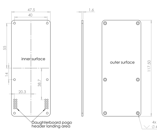
- phone back can be replaced with a PCB to expand the hardware capabilities
Software
- Fully working VoIP phone, with calling, text messages, and contact library.
- MicroPython for user applications *
* Python runs on a separate firmware image.
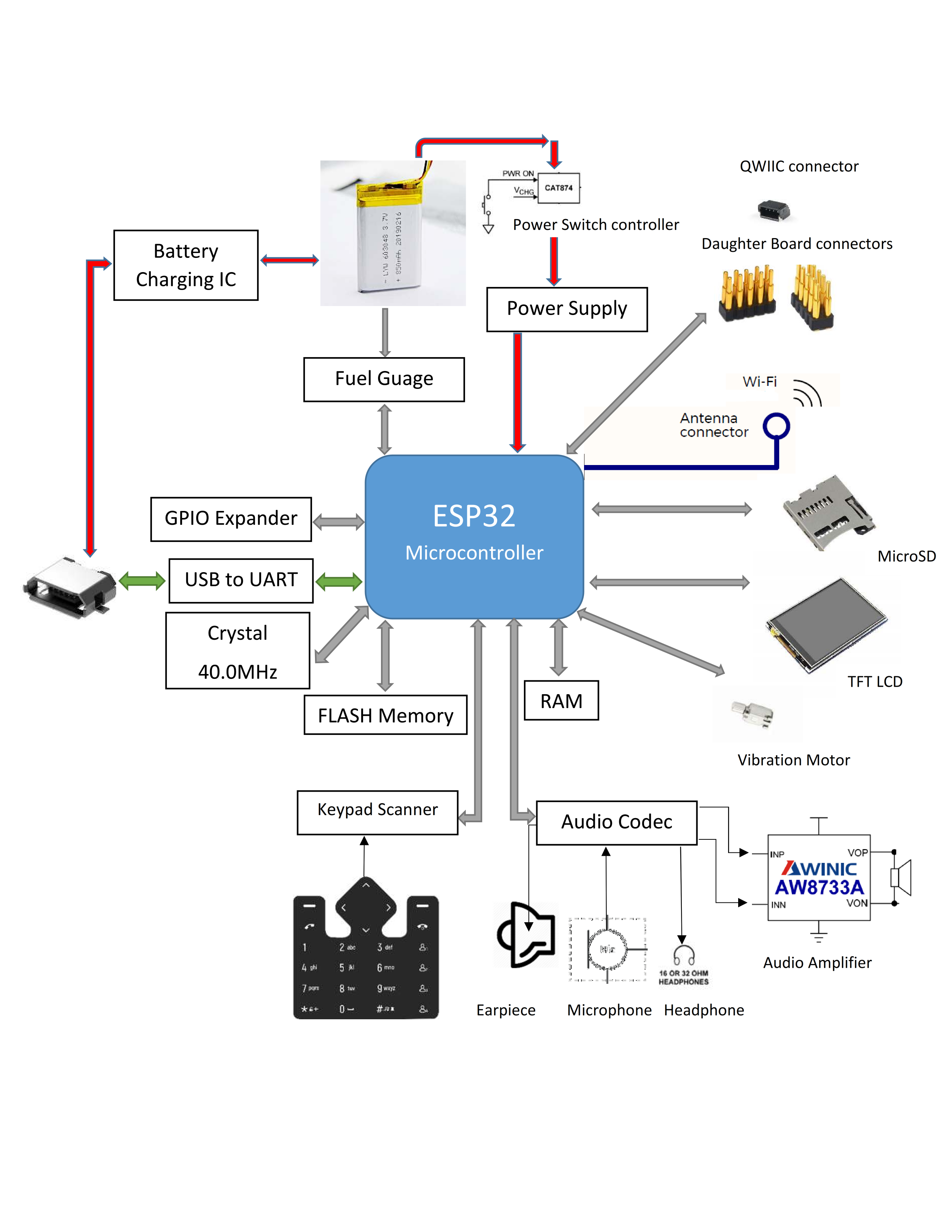
Block Diagram

Peripherals and GPIO
| Peripheral Type | Qty | Input(I) / Output(O) |
|---|---|---|
| Digital | 11 | I/O |
| Digital | 1 | I |
| Analog (ADC) | 5 | I |
| UART | 1 | I/O |
| SPI | 1 | I/O |
| I2C | 1 | I/O |
| USB-UART | 1 | I/O |
| PWM | 11 | O |
Pogo pins description
| Pin | Arduino Pin | Description |
|---|---|---|
| 5V | This pin is internally connected to the VBUS of USB port. | |
| VBAT | This pin is internally connected to the positive terminal of the LiPo battery connector. | |
| 3.3V | This pin is connected to the dedicated on board voltage regulator for daughter board. | |
| GND | This pin is connected to System GND. | |
| DB_RXD | 38 | Connected to Mainboard RX.Can be used as DIGITAL INPUT PIN(GPI_38) |
| DB_TXD | 32 | Connected to Mainboard TX.Can be used as DIGITAL PIN(GPIO_32), ANALOG PIN (ADC1_CH4) and PWM PIN |
| DB_SPI_MISO | 12 | MISO for Daughter board SPI. Can be used as DIGITAL PIN(GPIO_12) ANALOG PIN (ADC2_CH5) and PWM PIN. |
| DB_SPI_MOSI | 13 | MOSI for Daughter board SPI. Can be used as DIGITAL PIN(GPIO_13), ANALOG PIN (ADC2_CH4) and PWM PIN. |
| DB_SPI_CLK | 14 | Clock for Daughter board SPI. Can be used as DIGITAL PIN(GPIO_14), ANALOG PIN (ADC2_CH6) and PWM . |
| DB_SPI_CS | 27 | CS for Daughter board SPI. Can be used as DIGITAL PIN(GPIO_27), ANALOG PIN (ADC2_CH7) and PWM PIN. |
| I2C_SCL | 25 | Clock pin for I2C (GPIO_25).Not recommended for any other function. |
| I2C_SDA | 15 | Data pin for I2C(GPIO_15).Not recommended for any other function. |
| D0-D5 | EXTENDER_PIN(10) - EXTENDER_PIN(15) | These pins are generic IO pins connected to SX1509 IO expander |
Note
- The default drive strength of the ESP32 digital output pin is ~10mA.
- The default drive strength GPIO Expander digital output pin is ~8mA. Please refer to datasheet for further details.
5V PIN
The pin is internally connected to the VBUS of the USB port. The nominal output should be around 4.5 to 5 VDC when the device is plugged into the USB port and 0 when not connected to a USB source. You can use this pin to power peripherals that operate at such voltages. Do not exceed the current rating of the USB port, which is nominally rated to 500mA. This pin is also protected with an internal fuse rated at 1000mA.
Warning
5V pin is only recommend to use for powering load <100mA such as sensors and micro-controller. Not recommend for designs with high current requirement as voltage at this pin will drop below 4V at higher current due to drop at reverse voltage protection diode and current limiter.
VBAT Pin
This pin is internally connected to the positive pin LiPo Battery. Output voltage range on this pin is 3.4 to 4.2 VDC.
3.3V PIN
This pin is the output of the on board 3.3V LDO regulator (MIC5219-3.3BM5). The MIC5219 is designed for 150 mA to 200 mA output current applications where a high-current spike (500 mA) is needed for short, start-up conditions. Use can use this to power 3.3V devices.
Input only pins
GPIOs 34 to 39 are GPIs – input only pins. These pins don’t have internal pull-ups or pull-down resistors. They can’t be used as outputs, so use these pins only as inputs:
- DB_RXD (GPI 38)
HSPI
- DB_SPI_MISO(GPIO_12) MISO for Daughter board SPI.
- DB_SPI_MOSI(GPIO_13) MOSI for Daughter board SPI.
- DB_SPI_CLK(GPIO_14) Clock for Daughter board SPI.
- DB_SPI_CS(GPIO_27) CS for Daughter board SPI.
I2C
The ESP32 has two I2C channels and any pin can be set as SDA or SCL. When using the ESP32 with the WiPhone Board in Arduino IDE, the default I2C pins are:
- I2C_SDA (GPIO 15)
- I2C_SCL (GPIO 25)
Note
Don't Use I2C Pins for any other function .These Pins are connected to the I2C devices on the Phone and are not recommended for other functions.
UART (Serial)
- DB_TXD (GPIO 32)
- DB_RXD (GPI 38)
Analog to Digital Converter (ADC)
The ESP32 has 18 x 12 bits ADC input channels . These are the GPIOs that can be used as ADC and respective channels:
- DB_SPI_CS -> ADC2_CH7 (GPIO 27)
- DB_SPI_MOSI -> ADC2_CH4 (GPIO 13)
- DB_SPI_MISO -> ADC2_CH5 (GPIO 12)
- DB_SPI_CLK -> ADC2_CH6 (GPIO 14)
- DB_TXD -> ADC1_CH4 (GPIO 32)
- DB_RXD -> ADC1_CH2 (GPI 38)
Pins HIGH at Boot
Some GPIOs change its state to HIGH or output PWM signals at boot or reset. This means that if you have outputs connected to these GPIOs you may get unexpected results when the ESP32 resets or boots.
- DB_SPI_CLK (GPIO_14)
Interrupts
All GPIOs can be configured as interrupts.
D0-D5
These pins are generic IO pins connected to SX1509 IO expander and can be configured as Input/Output and PWM. In Arduino, these can be accessed as :
- D0 -> EXTENDER_PIN(10)
- D1 -> EXTENDER_PIN(11)
- D2 -> EXTENDER_PIN(12)
- D3 -> EXTENDER_PIN(13)
- D4 -> EXTENDER_PIN(14)
- D5 -> EXTENDER_PIN(15)
Radio specifications
Espressif Systems ESP32 for WiFi
| Feature | Description |
|---|---|
| WLAN Standards | IEEE 802 11b/g/n |
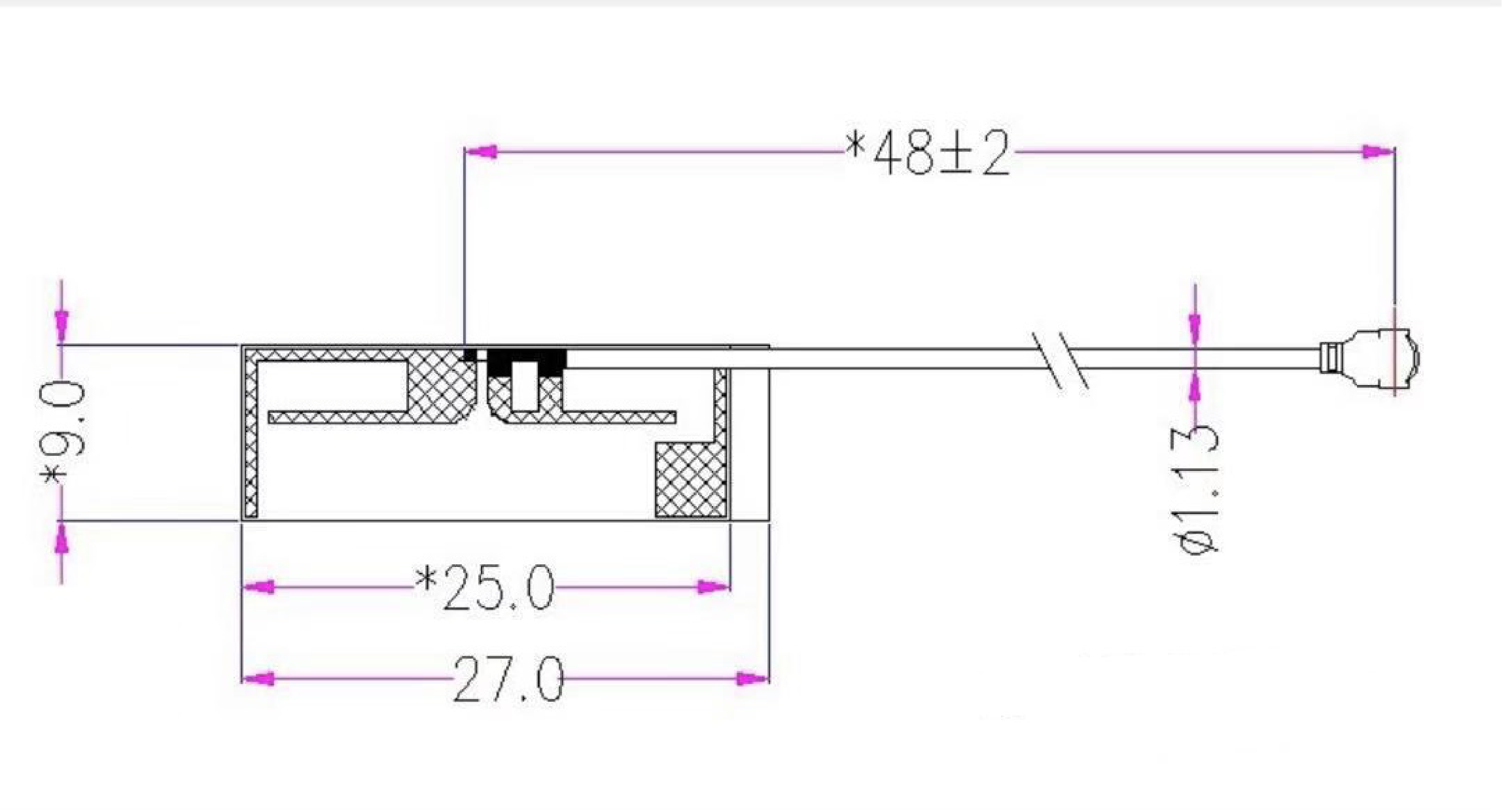
| Antenna Port | Single Antenna |
| Frequency Band | 2412 to 2472 MHz |
Note
WiPhone is Certified for Wi-Fi and Bluetooth but Bluetooth features of the ESP32 are not implemented in software.
Memory map
External SPI Flash Layout Overview
| Name | Type | SubType | offset | Size |
|---|---|---|---|---|
| nvs | data | nvs | 0x9000 | 0x5000 |
| otadata | data | ota | 0xe000 | 0x2000 |
| app0 | app | ota_0 | 0x10000 | 0x640000 |
| app1 | app | ota_1 | 0x650000 | 0x640000 |
| spiffs | data | spiffs | 0xc90000 | 0x370000 |
Absolute maximum ratings [1]
| Parameter | Symbol | Min | Typ | Max | Unit |
|---|---|---|---|---|---|
| Supply Input Voltage | VIN-MAX | -0.3 | +26.5 | V | |
| Battery Input Voltage | VBAT | -0.3 | +6 | V | |
| Supply Output Current | I3.3V-MAX | 500 | mA | ||
| Storage Temperature | Tstg | -30 | +75 | °C | |
| ESD Susceptibility HBM (Human Body Mode) | VESD | 2 | kV |
[1] Stresses beyond those listed under absolute maximum ratings may cause permanent damage to the device. These are stress ratings only, and functional operation of the device at these or any other conditions beyond those indicated under recommended operating conditions is not implied. Exposure to absolute-maximum-rated conditions for extended periods may affect device reliability.
Recommended operating conditions
| Parameter | Symbol | Min | Typ | Max | Unit |
|---|---|---|---|---|---|
| LiPo Battery Voltage | VBAT | +3.3 | +4.2 | V | |
| Supply Output Voltage | V3.3V | +3.3 | V | ||
| Operating Current (Radio ON) | IBAT avg | TBD | TBD | mA | |
| Operating Current (Radio OFF) | IBAT avg | TBD | TBD | mA | |
| Sleep Current | IQs | TBD | TBD | mA | |
| Deep Sleep Current (4.2V LiPo, Radio OFF) | IQds | TBD | TBD | uA | |
| Operating Temperature | Top | -20 | +60 | °C | |
| Humidity Range Non condensing, relative humidity | 95 | % |
Mechanical specifications

- Size: 120x50x12 mm
- Weight: 80g
- Polycarbonate case and screen
- Silicone keypad, Backlit
- Phone back is a replaceable PCB to expand the hardware capabilities.

Certifications and approvals
- Model Number: N0C311, N0C11P
- FCC ID: 2AHUL-9474663
- IC: 21408-9474663
- RoHS
- CE
- RCM
